Power over Ethernet (PoE) has revolutionized how power and data are transmitted over a single Ethernet cable, making it easier for network administrators to connect and power network switches, extenders, and other powered devices. This groundbreaking technology simplifies network installations for installers by eliminating the need for separate power cables, making it an efficient and cost-effective solution for various applications. Powered devices can now be easily connected using passive PoE, reducing the complexity of installation. This innovative solution benefits both installers and PoE devices. From IP cameras to wireless access points and VoIP phones, Power over Ethernet (PoE) is widely utilized in modern networks, providing power delivery (PD) and data transmission through standard Ethernet cabling. PoE switches (PSEs) support the PD of various devices, making them convenient and efficient for network setups. Network administrators benefit from the seamless integration of industrial PoE support with network switches and powered devices, streamlining operations while ensuring high-power efficiency. Industrial PoE injectors provide support for PDs. As gigabit Ethernet continues to dominate the networking landscape, understanding PoE pinout configurations and the power source becomes essential for maximizing its potential. With the rise of high-power devices, knowing how to switch between different power sources is crucial.
Exploring the Basics of PoE
IEEE Standards
Power over Ethernet (PoE) technology, as per the IEEE 802.3af/at/bt standard, enables network data devices to receive power via the Ethernet cable. This technology benefits network administrators, PD devices, and network installers. This standard specifies various power levels and requirements for network cables, ensuring compatibility across different PoE-enabled devices. Network administrators must understand and support these requirements when setting up a switch. For instance, IEEE 802.3af supports up to 15.4 watts of power for unmanaged PoE switches, while IEEE 802.3at can deliver up to 30 watts for industrial PoE devices. PoE injectors are also commonly used in these applications.
The PoE pinout, for example, is essential for network administrators when configuring a switch in PoE mode. It determines the arrangement of pins in an Ethernet connector to enable the transmission of both data and power. The pinout varies based on the PoE mode used, such as Alternative A or Alternative B, for delivering power over different pairs of wires within the Ethernet cable. For example, when connecting a switch to a budget, it is important to consider the pinout configuration. Additionally, make sure to enable cookies for optimal browsing experience.
PoE Modes
In Alternative A mode, one pair of conductors is used for data transmission while another carries electrical current for power delivery. This is a common example of industrial PoE devices working within a budget. Conversely, both pairs are simultaneously utilized for data and power transfer in Alternative B mode, making it an ideal solution for industrial PoE devices. Unmanaged PoE switches are also a great choice for those on a budget.
Understanding how distinct modes impact device connectivity at the infrastructure level is crucial when setting up a network with Power over Ethernet capabilities. This involves configuring the switch and staying within the allocated budget.
PoE Injectors vs Switches
When integrating PoE into a network setup, there are two primary techniques: using dedicated PoE injectors or employing switches with built-in PoE support. Both techniques allow for the mode of power delivery and help manage the power budget efficiently.
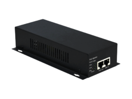
- PoE injectors are an efficient way to add Power over Ethernet capability to non-PoE switches or routers by injecting DC voltage into selected twisted-pair cables. This mode of operation is highly convenient for integrating PoE functionality into existing network infrastructure.
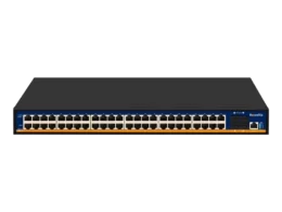
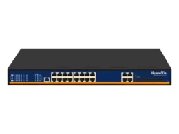
- On the other hand, PoEsupported switches feature built-in hardware that delivers power directly through their ports without requiring additional equipment like injectors.
PoE Standards and Protocols
Learn about the standards for power over Ethernet (PoE) technology that allows gigabit and Ethernet data to be sent on the same network cable.
IEEE 802.3af is the original PoE standard, delivering up to 15.4W of power per port to connected devices such as PoE switches or other compatible equipment. This standard allows for simultaneous data and power transmission over the same Ethernet cable, simplifying installation and reducing costs. It is especially useful when connecting devices to a switch, as it eliminates the need for separate power cables.
On the other hand, the IEEE 802.3at switch, also known as PoE+, takes power delivery a step further by providing up to 30W per port. This higher power capability makes it suitable for powering a broader range of devices, including high-power devices like PTZ (Pan-Tilt-Zoom) cameras, dual-band wireless access points, and more. The switch can handle the power needs of these devices effortlessly.
The latest advancement in PoE standards is represented by IEEE 802.3bt or PoE++, which can deliver up to an impressive 60W or even 100W of power per port, depending on the specific implementation used. This switch is a game-changer in terms of power delivery.
Power Sourcing Equipment (PSE) Types
There are two primary types of PSEs: endspan PSEs integrated into regular network switches that directly provide PoE midspan PSEs added between non-PoE network switches and powered devices to inject power into the Ethernet cable.
Endspan PSEs, also known as power budgets, are built into dedicated PoE switches designed specifically for supporting PoE-enabled devices without additional hardware requirements. Meanwhile, midspans can be added onto existing non-PoEswitches, providing them with support capabilities and expanding their power budget.
PoE Pinout and Cable Specifications
Pinout Configuration
The PoE pinout configuration follows a standardized pattern, ensuring that power is transmitted over specific pairs of wires within an Ethernet cable. This switch ensures efficient power distribution. This switch allows for safe and efficient power delivery alongside data signals. The pinout pairs used for the PoE switch are designed to carry power without interfering with data transmission.
For instance, in a standard 8-pin RJ45 connector, pins 1 and 2 form one twisted pair, while pins 3 and 6 make up another. This is important for power over Ethernet (PoE) switches. In a PoE application, these pairs deliver power from the source to the receiving device. This fixed polarity ensures that both ends of the connection can reliably identify where power is being sent and received.
Cable Recommendations
When setting up a PoE network, it’s crucial to utilize appropriate cabling to ensure optimal performance and safety within the power budget. Cat5e or higher-rated Ethernet cables are recommended for PoE installations due to their ability to simultaneously handle data and electrical power. These cables are specifically designed to minimize interference between the different wire pairs within them, providing reliable connectivity for both data transfer and powering devices.
Moreover, adhering to these recommendations helps mitigate potential issues such as voltage drop or heat generation within the cables when transmitting power over long distances. Quality cabling reduces the risk of damage or degradation caused by excessive electrical current passing through substandard wires, which can negatively impact the power budget.
Maximum Cable Length
It’s essential to consider cable length limitations imposed by power budget standards and practical considerations in PoE setups. The maximum cable length for PoE installations is typically limited to 100 meters (328 feet). Exceeding this distance can lead to signal loss or inadequate power delivery at the end device due to resistance in longer cable runs.
For instance, Cat7, Cat7a, or even more advanced options like Cat8 Ethernet cables, which support higher frequencies compared with their predecessors, may be employed while still adhering strictly to IEEE standards for maximum distance.
By incorporating these specifications into your planning process when implementing Power over Ethernet technology systems, you ensure proper functionality while avoiding potential issues related to inferior equipment.
Power Pin Assignments in PoE
Utilization of Pins
Pins 1/2 and 3/6 are dedicated to data transmission in a standard Ethernet cable. However, Pins 4/5 and 7/8 serve the crucial function of power delivery. While regular Ethernet cables use specific pins for transmitting data, PoE repurposes other pins to supply power.
For instance, understanding the pin assignments is essential if you’re using a device that requires both network connectivity and power through an Ethernet cable. Different standards may have varying pin assignments for transmitting power, so it’s important to know these variations based on the specific PoE standard.
Powered Pairs and Power Injectors
Delivering electrical power and data signals over standard twisted-pair cabling involves utilizing what are known as “powered pairs.” In this context, powered pairs refer to the specific wire pairs within an Ethernet cable that carry electrical current for powering devices connected at each end.
Moreover, power injectors play a critical role when considering PoE setups where additional power needs arise or where non-PoE switches need to support PoE devices. These devices enable non-PoE switches to provide power alongside data by injecting DC voltage into the unused wire pairs in an Ethernet cable.
Understanding how different versions of the PoE standard deliver DC voltage over unshielded twisted-pair wiring is vital. For example:
- The latest version can deliver up to 25 watts, depending on the version.
- Crossover MDI-X cables may invert the polarity of the DC supply, thus ensuring flexibility for powered devices operating with either spare pairs 4–5 and 7–8 or data pairs 1–2 and 3–6.
Benefits of Using PoE Technology
Simplifies Network Infrastructure
Using PoE technology simplifies network infrastructure by reducing the number of cables needed. With passive PoE, power and data can be transmitted over a single Ethernet cable, eliminating the need for separate power sources for devices like VOIP phones, wireless access points (WAPs), and IP cameras. This consolidation reduces clutter and streamlines the setup process, making it easier to manage and maintain.
This streamlined approach saves space and reduces installation time and costs. For instance, in an office setting where multiple devices such as IP cameras or WAPs are required, implementing PoE means fewer cables to run through walls or ceilings. With industrial PoE, businesses can enhance their operational efficiency by connecting various powered devices across large warehouses or manufacturing facilities without worrying about intricate wiring setups.
Flexible Device Placement
One of the key advantages of utilizing PoE technology is that it allows for flexible device placement without proximity to power outlets. This flexibility is particularly beneficial in environments where traditional power sources may not be readily available or accessible. For example, placing devices based on optimal network coverage rather than outlet location is invaluable when deploying security cameras outdoors or positioning wireless access points in expansive areas such as stadiums or campuses.
Moreover, with advancements in high-power PoE standards, even more demanding applications like LED lighting systems can benefit from this flexibility. By using a single Ethernet cable for data connectivity and power supply, organizations can significantly expand their options for device deployment while maintaining efficient energy management.
Centralized Power Management and Monitoring
Another significant advantage of PoE technology is its capability to enable centralized power management and monitoring of devices. Administrators have real-time visibility into each powered device’s status and consumption levels through a central Power Sourcing Equipment (PSE) switch or injector device connected to a network operation center (NOC).
For instance, when used with VOIP phones in an office environment, administrators can remotely monitor phone usage patterns and troubleshoot any issues related to power supply directly from their desks. Similarly, in smart home applications where POE powers LED lighting systems or sensors throughout the premises,
organizations gain greater control over energy usage while being able to respond promptly to any maintenance requirements.
Recognizing the Limitations of PoE
Power Limitations
The power limitations of specific PoE standards can restrict the use of high-power devices. For instance, some versions may not support power-hungry devices such as pan-tilt-zoom (PTZ) cameras or high-performance Wi-Fi access points. This limitation stems from the maximum power output allowed by the standard, which may not meet the requirements of these demanding devices.
When transmitting power over long cable lengths, there is a risk of voltage drop and reduced power delivery at the end device. If you use Cat7 or Cat8 Ethernet cables for a maximum distance of 100m, you might experience decreased power efficiency due to voltage drop along this extended length. As a result, it’s crucial to consider these factors when planning your PoE deployment to ensure that your powered devices receive an adequate and stable power supply.
Compatibility Issues
Another challenge with PoE technology involves potential compatibility issues when connecting non-PoE devices to PoE switches. Some legacy devices may not be capable of PD (powered device), thus causing problems when connected directly to a PSE (power sourcing equipment). A midspan power supply—an additional PoE power source—can resolve this issue by providing power injection compatible with non-PoE switches.
Installation Tips for PoE Systems
Ensuring Compatibility
When installing a PoE pinout system, it’s crucial to ensure that the network switches or injectors support the required PoE standard. This compatibility is essential for seamless integration and efficient power delivery. The PoE system may not function optimally without proper compatibility, leading to potential performance issues.
Certified PoE devices are equally important as they ensure compatibility and safety within the network infrastructure. Certified devices have been tested for reliability and adherence to industry standards, reducing the risk of malfunctions or safety hazards. Network installers can guarantee a smooth installation process by utilizing certified equipment while mitigating potential risks associated with non-certified products.
Proper Labeling and Documentation
Properly labeling and documenting PoE connections is an often-overlooked yet critical aspect of installation. By clearly marking each connection point and maintaining comprehensive documentation, network installers can streamline troubleshooting processes in case of any issues arising in the future. This proactive approach saves time and effort by allowing quick identification of specific connection points without extensive guesswork.
Integrating data and power on the same wires through a PoE pinout offers substantial cost savings compared to traditional wiring methods for lighting systems or other applications. The reduced installation costs make PoE an attractive option for various installations where minimizing upfront expenses is crucial. Operating costs are notably more efficient due to streamlined power delivery over Ethernet cables.
The structured cabling used in PoE systems remains safe from interference with concurrent network operations even when delivering data and power simultaneously. This feature enhances overall system reliability while simplifying maintenance procedures during installation or subsequent upgrades.
Managing Power Budgets in PoE Networks
Calculating Total Power Requirements
When dealing with power over Ethernet (PoE) networks, it’s crucial to calculate the total power requirements of all connected devices. This helps prevent exceeding the switch capacity and ensures that each device receives adequate power for optimal performance. For instance, if a network has multiple IP cameras, VoIP phones, and access points, administrators must add up their power needs to determine the overall power budget.
It’s important to note that different devices have varying power consumption levels. Some may only require 15W, while others might need up to 60W or even 90W power. Network administrators can avoid potential issues related to insufficient power supply by understanding these requirements and summing them up accurately.
Utilizing Managed PoE Switches
Consider using managed PoE switches with advanced features for better control over the power budget in your network. These switches come equipped with functionalities that allow administrators to monitor and allocate power efficiently based on the specific needs of connected devices. They also provide insights into real-time usage patterns, which can aid in making informed decisions regarding resource allocation.
Managed switches enable administrators to prioritize critical devices by allocating more power when needed while ensuring that less critical ones receive just enough without wasting resources. They offer greater flexibility in managing sleep modes or scheduling automatic shutdown during non-operational hours for further energy conservation.

Implementing Power-Saving Techniques
Implementing power-saving techniques is essential for optimizing energy consumption within PoE networks. One effective method is scheduling device sleep modes when not in use. For example, if an office environment has IP phones only used during business hours, scheduling them to enter sleep mode after work hours can significantly reduce unnecessary energy expenditure.
Furthermore, utilizing innovative lighting systems powered through PoE allows for intelligent management of lighting schedules based on occupancy patterns or natural light availability. This reduces electricity costs and contributes towards creating environmentally friendly workspaces by promoting sustainable practices.
Understanding RJ45 Pinout and Wiring
T568A and T568B
Two standards are widely used: T568A and T568B. The choice between these standards determines the arrangement of the eight color-coded wires inside the connector. For instance, in T568A, the green pair is on pins 3 and 6, while in T568B, it’s on pins 1 and 2.
These wiring standards are crucial for establishing a uniform approach to connecting Ethernet devices. They ensure that when you plug in a cable at one end using one standard, it will work correctly when connected to a device or network that uses the other standard.
Both standards have their merits; however, following either consistently within a network is essential for maintaining proper connectivity.
Power over Ethernet (PoE) Considerations
In PoE systems utilizing RJ45 connectors, the pinout configuration is vital. Incorrectly configured pinouts can lead to power issues such as insufficient power delivery or device damage due to overvoltage.
This aspect becomes even more critical when dealing with crossover MDI-X cables, which can invert the polarity of the DC supply. In such cases, understanding how each pair of wires carries power or data signals is imperative for ensuring seamless operation within PoE networks.
The IEEE allows two alternatives (modes) – “Alt-A” and “Alt B” – which provide flexibility in choosing how power is transmitted through different pairs of wires. This flexibility enables system designers to adapt based on specific requirements regarding data connection and powering needs within a given setup.
Conclusion on PoE Pinout and Applications
You’ve now gained a comprehensive understanding of PoE pinout, cable specifications, power pin assignments, and the applications of Power over Ethernet. With this knowledge, you can make informed decisions when implementing PoE technology in your network infrastructure. Remember to consider the installation tips and manage power budgets effectively for optimal performance.
As you delve into the world of PoE, keep exploring the evolving standards and protocols to stay ahead in the game. Whether you’re a tech enthusiast or a professional in the field, embracing the possibilities of PoE can revolutionize your approach to power delivery in networking. Get ready to power up your network with PoE!
Frequently Asked Questions
What is Power over Ethernet (PoE)?
Power over Ethernet (PoE) technology allows network cables to carry electrical power. This eliminates the need for separate power cables, simplifying installation and reducing costs.
How does PoE work?
PoE works by sending electric power alongside data on twisted pair Ethernet cabling. It uses either the unused wires in the cable or runs electricity over the same wires used for data transmission.
What are the benefits of using PoE technology?
Using PoE technology reduces installation time and costs provides flexibility in device placement, and enables centralized backup power. It also simplifies management by allowing remote monitoring and control of devices.
Are there any limitations to using PoE?
One limitation of PoE is its distance constraints; it typically operates within 100 meters from the switch. Due to PoE’s limited power delivery capabilities, high-power devices may require alternative powering methods.
How can administrators manage power budgets in a PoE network with pair ethernet and gigabit ethernet? By using the appropriate pair cable.
To manage power budgets effectively, calculate the total wattage required by all connected devices, including PDs (Powered Devices) and PSEs (Power Sourcing Equipment). Ensure that your PSE has sufficient capacity to deliver this total wattage.