Introduction
In recent years, the country has been increasing its investment in major infrastructure construction such as railroads, highways, and airports. The transportation industry has put forward higher requirements on communication networks’ reliability, real-time, and stability. HoweVision Technology has conducted extensive market research to fully understand the high-reliability demand of the transportation industry for the terminal equipment access network. Based on the existing products and technologies, we have developed highly reliable, intelligent, and industrial-grade products to meet the communication requirements of the transportation industry.
By 2020, China’s urban rail transit planning lines 176, total mileage of 6200 km. Two thousand fifty planning lines will increase to 289; the unlimited mileage will reach 11,700 km. The investment scale of rail transit has exceeded 1 trillion yuan by 2020. The construction of a rail transit communication network is related to the operation of the whole rail transit. Therefore, communication equipment’s reliability, stability, compatibility, and flexibility are receiving more and more attention.
The rapid development of China’s rail transit has accumulated rich communication experience in transmission solutions for HoweVision, which has laid a solid foundation for better service of global rail transmission solutions.
Analysis of communication pain points in Rail Transit
- rail transit has higher data and signal accuracy and low latency requirements.
- Particular power environment, with broader standards for power supply system for equipment and systems.
- There are high information security requirements, large-scale private networks, higher security requirements, and large-scale equipment networking capabilities.
- There are multi-level redundancy combination applications, the industry lacks professional communication products, and manufacturers need more integration.
- Track video high-speed multi-frame, the large amount of video information. Professional video communication equipment is needed to solve the delay lag and optimize the smoothness of video information.
Brief description of Rail Transit Communication System
The rail transit communication system consists of a backbone network that is the transmission system and each subsystem network, and each design is both independent and interrelated.
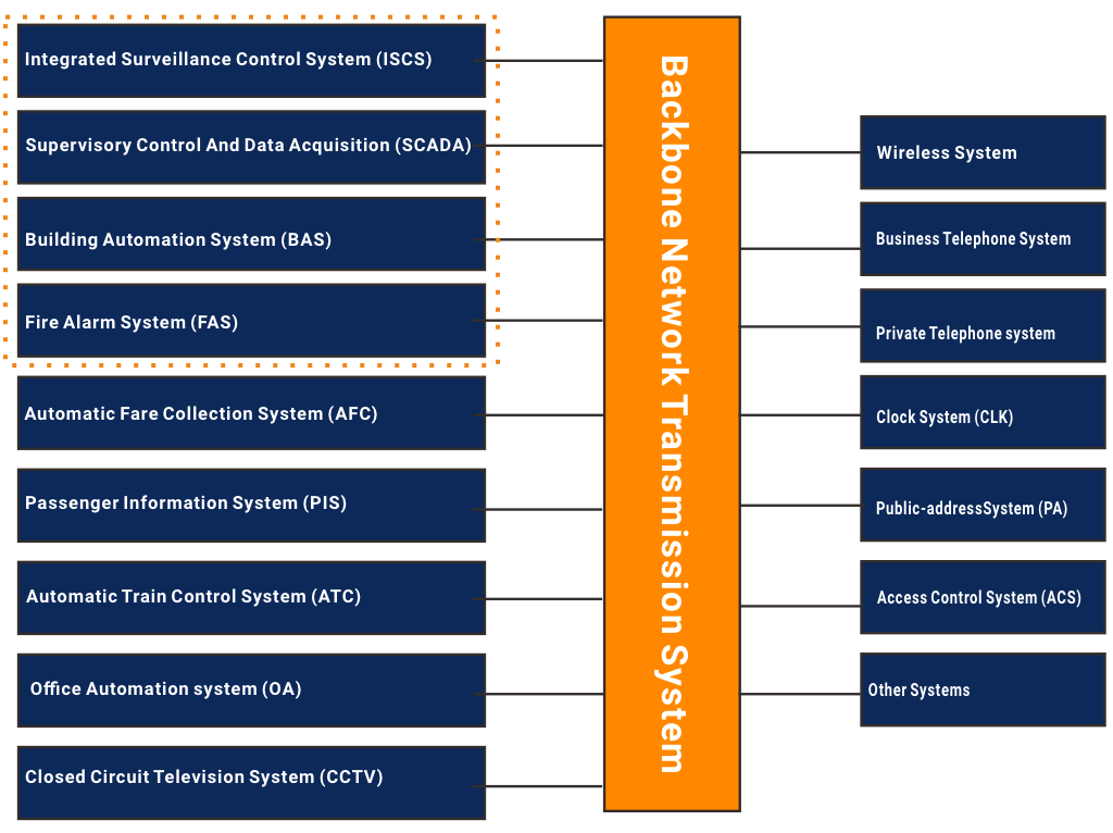
- Systems based on TDM channel transmission: wireless system, centralized alarm system, official telephone system, unique telephone system, broadcasting system, clock system, etc.
- Systems based on Ethernet channel transmission: integrated monitoring system, automatic ticketing system, passenger information system, train automatic control system, office automation system, closed-circuit television monitoring system, etc.
The backbone network of railway communication systems, i.e., transmission, is mainly realized by ATM, SDH, MSTP, or OTN systems. Based on optical fiber, it recognizes the integrated service transmission of various information such as voice, data, and image. In the line control center, station, vehicle section, and parking lot of rail transit, interfaces are reserved for accessing the integrated monitoring system (ISCS), automatic ticketing system (AFC), passenger information system (PIS), automatic train control system (ATC), office automation system (OA), closed-circuit television monitoring system (CCTV), centralized alarm system (ALM), official telephone system, unique telephone system, wireless communication system, broadcasting system (PA), clock system (CLK) and other subsystems.
Each subsystem of urban rail transit generally adopts the structure mode of two levels of management (main level, station level) and three levels of monitoring (main level, station level, site level).
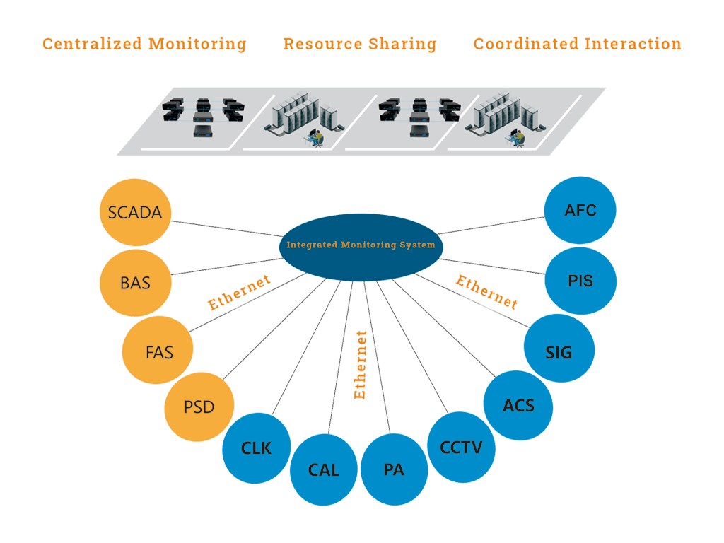
Integrated monitoring system
It is a powerful, open, modular, and scalable distributed control system, integrating and interconnecting several subsystems, mainly integrating the power monitoring subsystem (SCADA), environment and equipment monitoring subsystem (BAS), fire alarm subsystem (FAS), screen door subsystem (PSD), interconnecting automatic ticketing system (AFC), passenger information system (PIS), closed-circuit system (PIS), and other subsystems. (PIS), closed-circuit television monitoring system (CCTV), centralized alarm system (ALM), signal system, broadcasting system, clock system (CLK), and other subsystems. It realizes rail transit information interoperability and resource sharing, enhances automation level, and improves the subway’s safety, reliability, and responsiveness.
Automatic ticketing system
It is a computer-controlled automated network system of automatic ticketing, automatic charging, and statistics. It can realize the automation of rail transit ticketing, checking, billing, charging, statistics, scoring, and management. The automatic ticketing system divides into five application layers.
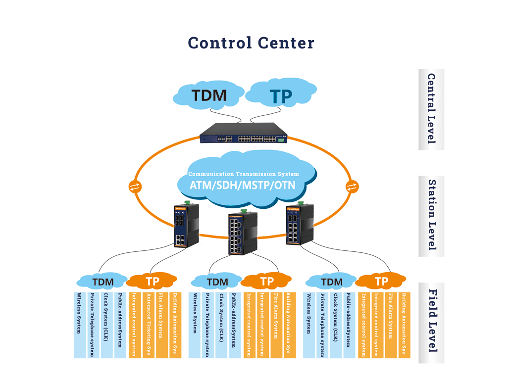
Passenger information system
It is a system that relies on multimedia network technology, takes a computer system as the core, and provides information service to passengers through the medium of stations and onboard display terminals.
It can divide into control center subsystem, station subsystem, onboard subsystem, and network subsystem (wired network and wireless subsystem). The onboard and network subsystem are the core parts of the passenger information system.
CCTV Monitoring System
Operation managers mainly monitor the passenger flow, train entry and exit, and passenger boarding and alighting. It is used to strengthen the operation organization and management, improve efficiency, and ensure passengers’ safe and punctual transportation. With the gradual improvement of Ethernet and related hardware technology, IPcam has been widely used. Video surveillance has gradually evolved into the ultra (high) definition and low latency era. HD video is mainly transmitted to the station monitoring room using industrial network products and then summarized by the communication network to the line control center, which carries out centralized monitoring and unified management.
Centralized Alarm System
The alarm information of each subsystem in the communication system is collected and processed centrally. The communication network provides a transmission interface. The communication network includes a transmission interface.
Official Telephone System
It is a fixed communication service for the management department, operation department, maintenance department, and other related departments of each station, vehicle section, and control center of rail transit to provide official communication, including telephone service and part non-telephone service. In case of a significant failure of the rail transit dedicated telephone system, It uses the official telephone system as an emergency communication means for the dedicated telephone. The communication network provides the transmission interface.
Private Telephone System
It is an essential communication tool for control center dispatchers and station/vehicle section officers to direct train operations and dispatching orders. It is a particular communication system that provides command means for train operation, power supply, disaster prevention and rescue, and ticket management. A communication network provides the transmission interface.
Wireless Communication System
It is the only means of communication between high-speed subway trains and station operation managers. It is responsible for the critical mission of improving operational efficiency and ensuring the safety of traffic and the lives of subway passengers. It provides a wireless communication guarantee for train dispatching, maintenance dispatching, disaster prevention, environmental control dispatching, vehicle section dispatching, etc. The communication network provides the transmission interface.
Broadcasting System
It is used to broadcast announcement information to the personnel in the building. It is also used for disaster prevention, posting when disasters occur, and guiding personnel to evacuate safely. It uses to broadcast information to operation and maintenance personnel. The communication network provides the transmission interface.
Clock system
Provide a unified standard time signal for metro staff, passengers, and related systems. The communication network provides a transmission interface.
HoweVision Technology summarizes the needs of the rail transit communication system. It proposes to build a redundant network based on the backbone network of the transmission system and according to the different needs of each design. Construct redundant networks for several essential systems. Ensure redundant protection of important service transmission links to achieve reliable transmission in harsh field environments.
Integrated Monitoring System (ISCS) communication solution
Composition of the integrated monitoring system
The main functions of the integrated monitoring system include the real-time centralized monitoring of mechanical and electrical equipment and the coordination and linkage functions between the systems. On the one hand, the integrated monitoring system can realize real-time centralized monitoring and control of electric power equipment, fire alarm information and its equipment, station environmental control equipment, inter-district ecological control equipment, ecological parameters, screen door equipment, flood prevention door equipment, escalator equipment, lighting equipment, access control equipment, automatic ticketing equipment, broadcasting, and closed-circuit TV equipment, broadcast information and clock information of passenger information display system, etc. On the other hand, the integrated monitoring system can also realize the coordination and interaction among the related systems and types of equipment under non-operating conditions at night, normal operating conditions during the daytime, emergency and unexpected situations, and essential equipment failure conditions.
The integrated monitoring system adopts a hierarchical distributed structure with two levels of management: Central level (CISCS), station level (SISCS), and bottom equipment control level (field level). The system has a two-tier network structure. The station-level and central-level local monitoring networks are built using industrial Ethernet, with 10M/100M dual-star redundant Ethernet at the station level (including vehicle section/parking lot). The main group adopts 100M/1000M dual-star redundant Ethernet. The communication transmission network provides the backbone transmission network connecting the station-level and central-level systems. The communication network provides dual redundant backbone transmission channels for the comprehensive monitoring system in the control center, stations, vehicle sections, and parking lots, and the interface form is 10 Gigabit Ethernet.
The integrated monitoring system adopts highly reliable network and computer products such as industrial Ethernet switches, servers, and industrial control machines with good generality, international standards, or industry standards to build a unified hardware integration platform, which is modular. Customized application software is similar to the building block structure of a multi-layer software development platform. The standard open hardware interface and software communication protocol are used to realize information exchange with each access system in an integrated and interconnected way. Finally, it recognizes each related electromechanical equipment’s centralized monitoring and control function and the interoperability, information sharing, and coordination between systems.
The domestic new line integrated monitoring system is currently used in the depth system integration mode. This integrated model system (SCADA, BAS, FAS, PSD, etc.) connects to the station-level local network of the integrated monitoring system. The kit of interconnected systems (AFC, PIS, SIG, ACS, CCTV, PA, CLK, etc.) connects to the front-end/front-end processor FEP, which can convert various hardware interfaces and software protocols. At the same time, it can effectively isolate the data of ISCS and each subsystem. ISCS obtains the data of subsystems through FEP, and likewise, it completes issuing data and commands through FEP.
The integrated system means that all subsystem information is transmitted through the integrated monitoring system platform, and the subsystem no longer needs to provide an operator interface. All the subsystem operations are entirely done through the operation interface of ISCS, and under normal circumstances, the integrated subsystem depends on ISCS to achieve normal operation functions.
An interconnection system means that the integrated monitoring system only integrates the relevant and necessary information in the subsystem. The interconnected subsystem has an independent and complete operation interface, equipment, and network. It can operate independently from the ISCS under normal conditions and entire regular and emergency operations by itself. The interconnection system only uploads some information required for operation to the integrated monitoring system to realize the information interchange and coordination function among all electromechanical systems.
Integrated monitoring system communication solution
The integrated monitoring and interconnection systems are equipment status information and control information with small bandwidth requirements. The integrated monitoring system provides a 10/100M Ethernet interface for each system to meet each subsystem’s transmission bandwidth requirements.
Station-level and central-level local monitoring networks are with HoweVision Technology’s three-layer industrial Ethernet switches. The station level (installed in each station, vehicle section/parking lot) adopts 10M/100M dual-star redundant Ethernet. The central level (set up in the control center) assumes 100M/1000M dual-star redundant Ethernet.
The central-level integrated monitoring and control system (CISCS) has two three-tier industrial Ethernet switches with mutual redundancy. It provides 100M/1000M Ethernet access for two sets of local redundant real-time servers, two sets of redundant history servers, disk arrays, various dispatcher workstations (e.g., ESC, Loop ESC, Maintenance ESC, and General ESC, etc.), NMS workstations, event printers, report printers, color graphic printers, two sets of front-end/pre-processor FEP, etc.
The station-level integrated monitoring system (SISCS) and the vehicle section integrated monitoring system (DISCS) are equipped with two three-tier industrial Ethernet switches. They are redundant and provide 10M/100M Ethernet access for two local redundant real-time servers, two sets of front-end/pre-processors (FEP), two workstations, event printers, and Report printers station integrated backup panels (IBP), etc.
SCADA, BAS, FAS, and PSD systems integrate with the industrial Ethernet switch of the central level, station level, and vehicle section integrated monitoring system. AFC, PIS, ACS, PA, and CCTV subsystems are interconnected with the industrial Ethernet switch of the central level or station level integrated monitoring system through the front-end/front-end processor (FEP). Different services are isolated through VLANs, and Qos is set to ensure priority transmission of important service data.
Power Monitoring System communication solutions
A railway power monitoring system usually includes:
- A dispatching master station system.
- A substation integrated automation system.
- A communication channel.
Among them, the control center posting master station system exchanges information with the central control unit of the substation through the communication channel provided by the communication profession. The substation integrated automation system communicates with the IED devices in the substation through the communication channel and the network of the substation and the dispatch master station. The substation integrated automation system consists of the station control master unit and the communication network and IED devices in the substation.
The integrated automation system of the substation is the recombination and optimization design of the functions of the secondary equipment of the substation (including control, signal, measurement, protection, automatic device, remote device, etc.) by using microcomputer technology. It is a comprehensive automation system that automatically monitors, measures, protects, controls, and communicates with the dispatcher.
The comprehensive automation system of the substation is the controlled station of the power monitoring system, and the power monitoring system is integrated with the complete monitoring system at the station (vehicle section, parking lot) level. Its station (vehicle section, parking lot) level, center level, and backbone transmission network are unified by the comprehensive monitoring system. The substation integrated automation system adopts the mode of centralized management and decentralized arrangement, with a hierarchical and distributed system structure. It consists of station-level management, network communication, and interval equipment (measurement and control protection devices, intelligent monitoring units). The network communication layer realizes the communication between the station-level management layer and the interval equipment layer in the substation and the communication between the comprehensive automation system and the comprehensive monitoring system in the substation.
Due to the continuity and importance of the power business, the substation network communication layer must guarantee redundant communication capability in case of a single point of failure. The communication equipment must adapt to the harsh environment of the power site while having port expansion capability.
The redundant industrial Ethernet switches deployed in substations are modular and fanless in design, with high reliability and strong environmental adaptability. It complies with the IEC61850-3 substation standard and IEEE-1613 power industry standard and has passed KEMA international authoritative power industry certification. The industrial Ethernet switch for typical traction buck hybrid substation and parking lot hybrid substation is equipped with 12 fiber optic Ethernet interfaces and 8 RJ45 electrical Ethernet interfaces. The industrial Ethernet switch in a typical step-down substation is equipped with eight fiber optic Ethernet interfaces and 8 RJ45 electrical Ethernet interfaces. Two fiber optic Ethernet interfaces are added for each additional substation. The industrial Ethernet switch of the vehicle section traction step-down hybrid substation is equipped with 16 fiber optic Ethernet interfaces and 8 RJ45 electrical Ethernet interfaces.
The interval equipment layer of the substation realizes fiber-optic upload of power monitoring service through the photoelectric converter. It connects to the station-level management industrial switch in the substation.
Environment and Equipment Inspection system communication solutions
The environment and equipment monitoring (BAS) system is a comprehensive system to control and manage equipment such as building water supply and drainage, subway ventilation and lighting, passenger guidance, escalators, and elevators.
As an essential part of the integrated monitoring system, the BAS system is responsible for monitoring station E&M equipment and disaster prevention and relief in case of emergency. Due to the wide distribution of station mechanical and electrical equipment, the BAS system’s core controller and remote IO are generally connected through network communication. With the development of urban rail transit technology, domestic and foreign metro environment and equipment monitoring plans have gone through the separation stage of stations and entered a new phase of the network of the whole line. Equipment monitoring mainly adopts the system mode of decentralized control and centralized management. There are mainly two forms of Fieldbus and industrial Ethernet for BAS system field-level network.
Fieldbus technology has various disadvantages, such as difficult conversion between different standards, poor compatibility, and multiple barriers to system integration. On the other hand, Industrial Ethernet has the advantages of a standardized protocol, strong compatibility, and mature technology. With the continuous progress of global industrial automation technology, the BAS system network is developing from Fieldbus to industrial Ethernet.
Comparison of Industrial Ethernet and Fieldbus Technology
The domestic urban rail transit BAS system generally adopts PLC equipment, which is a network-based automation system involving various communication and network technologies. Due to the diverse Fieldbus standards (decided by the difference of each manufacturer’s technology), how to unify the Fieldbus standard has gone through many years of standard war. Finally, no unified standard has been formed. Multiple criteria are equal to no means, so both end-users and manufacturers are generally concerned about developing Fieldbus technology and seeking high-performance and low-cost solutions. Ethernet technology has achieved great success worldwide due to its openness, stability, and reliability. Therefore, improving Ethernet technology and making it suitable for digital communication in the field of industrial control has become a popular research direction in the industry in recent years. Many people hope that the Fieldbus technology will be unified based on Ethernet technology and change the current status quo of multiple standards coexisting. At the same time, Ethernet is used to unify all levels of industrial control networks and achieve truly seamless information integration. With the development of industrial Ethernet, the field-level network of BAS systems is upgraded from Fieldbus technology to industrial Ethernet technology. With its excellent quality, HoweVision’s industrial Ethernet communication products provide a reliable guarantee for the networking of the BAS system.
Environmental and Equipment Monitoring System Communication Solutions
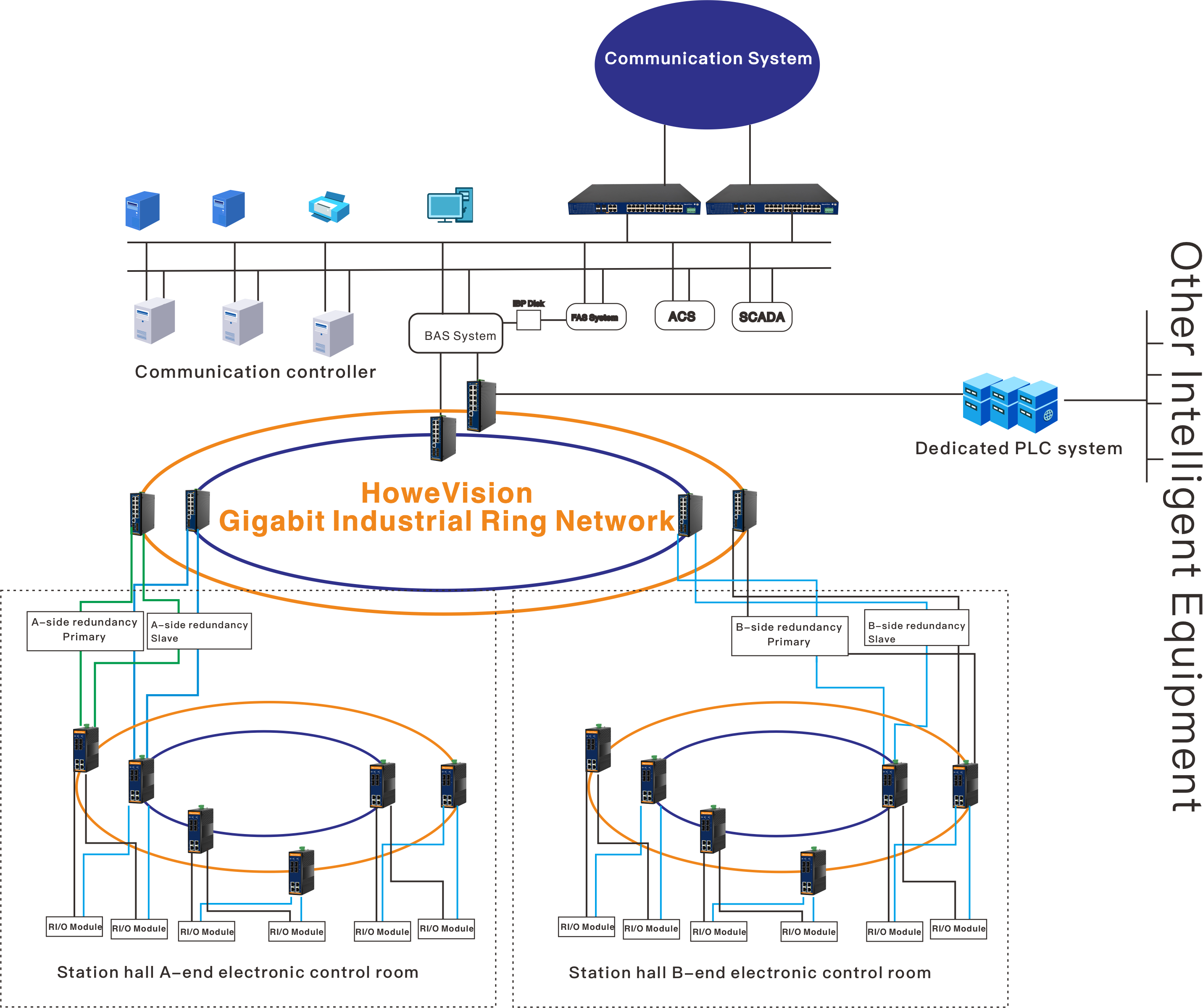
In the traditional dual Fieldbus solution, the redundant PLCs at each station is responsible for the BAS system equipment at one end. Some equipment needs to be operated in linkage, such as the link of fans and dampers distributed at different station ends in normal mode. The redundant PLCs at each end of the station are responsible for the BAS system equipment, such as the linkage of fans and dampers at different station ends in normal mode and the link of air conditioning systems at both ends in fire mode. In the conventional metro design, the redundant PLC at both ends of the station adopts the hot standby mode, configured with two backplanes, two CPUs, two power supplies, etc. But all modules are placed in the same room or even in the same control cabinet; when a fire or power failure occurs in the room, it is easy to cause the overall loss of the redundant PLC. And once the redundant PLC at one end is out of service, the redundant PLC at the other end may lead to the overall system failure due to interlocking action failure. Parallel wiring is used between PLC and R I/O, and the two buses are distributed close to each other in the local control box. In case of fire or other particular circumstances, it is effortless to cause the two buses to be interrupted simultaneously, resulting in the loss of contact between the system and R I/O.
HoweVision Technology proposes deploying dual redundant Layer 2 industrial Ethernet switches to form a gigabit fiber self-healing ring network to connect the redundant PLCs at the two ends of the station hall. The ITU-G.8032 ring network protocol is enabled, and the self-healing time reaches milliseconds (less than 20ms). If one end of the redundant PLC has an overall failure and withdraws from service, the system will immediately switch to the other end of the set of redundant PLC to continue working. It ensures that the system can operate normally under terrible conditions and that the commands issued by the central station can transmit to the field equipment.
The fiber optic ring network based on industrial Ethernet adopts distributed wiring (with breakpoint protection function), and the fiber optic is spread into a ring in the station. In case of fire or other special conditions, the bus will immediately switch the transmission path, which will not cause an interruption of communication between PLC and R I/O. The primary transmission medium in the traditional dual Fieldbus solution is the communication cable. In the complex environment, the communication cable is easily disturbed by various electromagnetic interference sources in the metro. Using a fiber-optic medium can avoid the influence of electromagnetic interference on the system from the root. The electromagnetic compatibility of HoweVision Technology equipment itself reaches industrial level 4, which greatly ensures the stability and reliability of transmission in a complex environment.
Technical Advantages of Integrated Monitoring System Communication Solution
High redundancy protection mechanism
The central-level integrated monitoring system (CISCS), station-level integrated monitoring system (SISCS), and vehicle section integrated monitoring system (DISCS) adopt double-star redundant industrial-grade networks to guarantee the real-time and reliability of the link.
The core equipment enables VRRP (Virtual Routing Redundancy Protocol) to provide a redundancy guarantee for the routing of the whole system. When one Layer 3 switch fails, the backup Layer 3 switch takes over the forwarding work in time to provide transparent switching to users and improve the network service quality.
The BAS system communication network adopts ITU-T G.8032 Ethernet loop protection, which genuinely solves the problems of multi-loop security, arbitrary topology, multi-domain safety, and multi-protocol interoperability.
Industrial-grade Isolated Power Supply
The power load of the ISCS system is a primary load with a 2-way power supply. HoweVision Technology’s industrial Ethernet switch’s power supply is AC220V, which supports dual power supply access to ensure the switch is not powered when the single-way power supply fails. The industrial-grade isolated power supply module effectively prevents the power supply system from bringing abnormal power supply to the switch under the combined effect of transient voltage and temperature drift, resulting in the switch crashing, frequent reboot, and severe packet loss.
Multi-level EMC Protection Measures
Interference sources of rail transit are mainly divided into fixed interference sources and mobile interference sources. Selected interference sources include line discharge and traction substation equipment, and mobile interference sources include internal equipment of locomotives and contact points of pantographs and conductors. The radio noise generated by the pantograph sliding offline on the wire of the contact network is not only the most severe source of electromagnetic interference in the electrified railroad but also the source of interference that affects the most factors of its strength and weakness. HoweVision Technology industrial Ethernet switch adopts shielding, grounding, filtering, and isolation measures to improve the anti-interference capability of the switch, which complies with IEC61000-4 series and industrial-level electromagnetic compatibility standards such as EN50121, EN55011, and EN55022.
High Reliability
With industrial-grade chips, industrial-grade circuit design, fanless wide temperature design, low power consumption, and a full range of triple-proof protection measures (triple-proof means moisture-proof, salt spray-proof, and mold-proof). The MTBF value of the switch can reach 35 years, providing a guarantee for the reliability and stability of the entire system communication.
High Protection Design
Onboard communication uses M12 interface IP67 high protection products, fastening type Ethernet access method, dustproof, waterproof, and anti-vibration shock design. And can be customized fixed bracket, equipped with a shock absorption piece, to meet the subway / large vibration shock requirements. It prevents loose wiring and abnormal communication caused by vibration during high-speed train operations and emergency stops. Industrial grade design uses shielding, grounding, filtering, and isolation measures to improve the anti-interference capability of the switch, which complies with the IEC61000-4 series and industrial-grade EMC standards such as EN50121 EN55011 and EN55022. It has passed the relevant certifications of the Ministry of Railways, the Academy of Railway Sciences, and the EMC laboratory of Beijing Jiaotong University.
Safe and Reliable Switching Network
Adopting the mixed networking mode of onboard three-layer switch + two-layer switch can realize the fault isolation for each train. The conventional design scheme is a two-layer networking scheme that cannot realize each car’s independent fault isolation.
Note: Fault isolation refers to broadcast message isolation, where a broadcast storm occurs in the internal network of a single train, affecting other trains and the entire wireless network. The car ground to the center is a sizeable two-layer network. If the car network is also planned as a two-layer network, then to avoid the formation of loops between the car ground caused by broadcast storms, the APs in the front and rear of the car must not work simultaneously. Suppose a diverse network of Layer 3 switch and Layer 2 switch is used. In that case, the physical isolation between trains can be realized by the Layer 3 routing function of the driver’s room switch, which significantly enhances the security and reliability of the network.
The network solution using onboard Layer 3 switches (supporting OSPF routing protocol, PIM multicast protocol, and VRRP) can realize the functions of primary and backup switching (VRRP function) and narrow broadcast domain.
High Transmission Efficiency
It provides a high-quality QoS guarantee, provides different priority services for additional services, and determines bandwidth according to the priority, ensuring high efficiency of data transmission of the whole network and setting bandwidth limits for the corresponding service ports. Support IGMP Snooping to avoid causing multicast flow storms and wasting network bandwidth. Support VLAN to realize broadcast domain isolation, separate different types of service traffic, limit broadcast messages flooding in the whole network, and control broadcast storms.
Recommended essential products of rail transportation
10 Gigabit Layer 3 Core Ethernet Switches

- Key Feature:
- Cache up to 12Mbit can meet the smooth transmission of 4K video
- Support IEEE802.3/802.3u/802.3ab/802.3z/802.3x store-and-forward mode
- Supports large backplane bandwidth and large switch cache to ensure wire-speed forwarding of all ports
- Support ITU G.8032 standard ERPS ring network protocol, self-healing time less than 20ms
- Support the international standard IEEE 802.3D/W/S standard STP/RSTP/MSTP protocol
- Support static routing, RIPv1/v2, OSPFv2
- Redundant dual power supply DC/AC power specifications optional, anti-reverse connection, over-current protection function
- -40℃~85℃ wide temperature design, ensure the equipment adapts to the various harsh field environment
Industrial 14-Ports Gigabit L2+ Managed Ethernet switch
- Model: IS50824GFM
- L2+ Managed industrial Gigabit Ethernet switch,
- Support 802.1Q VLAN, Mirroring, Port isolation, IGMP, DHCP, LLDP, DDM.
- Support spanning tree STP(802.1D) and RSTP(802.1W). MSTP(802.1S).
- Support management through WEB, CLI, TELNET, SSH, and SNMP(V1, V2, V3).
- 5 years warranty.
- OEM/ODM is available
- Small MOQ is welcome
Industrial Gigabit Ethernet PoE Switch, 8 Ports POE+, 2 Ports SFP Uplink
- Model: IPS8G2GF
- Unmanaged Industrial Gigabit Ethernet Switch PoE
- 9-56V DC redundant power with polarity reverse protect
- -40 to 75 degrees C operating temperature
- IP40 aluminum case without Fan
- 5 years warranty.
- OEM/ODM is available
- Small MOQ is welcome
Rail Traffic Success Story
- Beijing Metro Line 9 Beijing Subway Company Infrastructure Network Construction and Access Project
- Tianjin Metro Jimbin Light Rail Line 9 Station to Station Microcomputer Interlocking System
- Tianjin Metro Jinbin Light Rail Line 9 Public Service Telephone System
- Tianjin Metro Jinbin Light Rail Line 9 Dedicated Wireless Trunking Communication System
- Tianjin Metro Line 5 AFC System
- Tianjin Metro Line 6 AFC System
- Tianjin Metro Line 5 PIS System
- Guangzhou Metro Line 6 Main Substation Dispatching System
- Guangzhou Metro Line 4 CCTV System
- Guangzhou Metro CCTV System for Line 7
- Guangzhou Metro CCTV System for Line 8
- Guangzhou Metro Line 9 CCTV System
- Guangzhou Metro Line 13 CCTV System
- Shanghai Metro Line 11 CCTV System
- Shanghai Metro Line 13 CCTV System
- ON-BOARD WIRELESS INTERNET SYSTEM FOR SHENZHEN METRO LINE 1
- ON-BOARD WIRELESS INTERNET SYSTEM FOR SHENZHEN METRO LINE 2
- ON-BOARD WIRELESS INTERNET SYSTEM FOR SHENZHEN METRO LINE 4
- Line 2, Suzhou Rail Transit
- Line 4, Suzhou Rail Transit
- Line 2, Suzhou Rail Transit, dedicated integrated access system
- Wuxi Metro Line 1 MSAP equipment installation project
- Line 4, Wuhan Metro, Phase I Public Mobile Network Co-Construction Project
- 20M circuit rental for MTR Station in the southern district, Qingdao
- Ningbo Metro Line 1 Phase I project Public Security Communication System Integration (Phase I) project
- Nanning MTR Project Command Office LAN works
- ONBOARD COMMUNICATION SYSTEM FOR R 1 line of Chengdu Xinjin tram demonstration line in Sichuan Province
- Video Monitoring System for Xinguanjiao section of Qinghai