
With the rapid development of the IoT industry, IP service has become the primary communication mode of IoT.
Traditional network communication has the following two defects:
- With the increase of packet services, standard SDH equipment cannot handle large-scale services well and is prone to network congestion.
- Due to connectionless and best-effort transmission characteristics, traditional Ethernet switch equipment cannot meet the requirements of transmitting TDM services and highly reliable, real-time data services.
In response to these shortcomings, MEF (labeled: Metro Ethernet Forum (MEF) is a non-profit organization focused on solving Metro Ethernet technology problems) has proposed the concept of operational-grade Ethernet. Operational Ethernet enables packet transport and high-quality multi-service bearers by enhancing the carrier-grade service capabilities of Ethernet. It overcomes the shortcomings of Ethernet in terms of reliability, quality of service QoS, scalability, synchronization, and security.
Network reliability is an essential feature of operational Ethernet. To prevent the failure of a link on the network, operational Ethernet requires a protection reversal capability within 50ms. The protection reversal technology mainly includes ring protection and linear protection. Two paths connect the two devices on the Ring for two devices on the Ring, which can achieve the most economical redundancy protection, so the ring technology is the current research hot spot. Major equipment vendors and standardization organizations are promoting the development of ring protection technology and standards. The application of ring protection technology in operational Ethernet is the focus of research in industrial communications.
HoweVision has worked in industrial communication for more than ten years with industrial PoE switches as its leading core product. HoweVision has used various protocols (STP, RSTP, MSTP, EAPS, RRPP, ZESR, ESR, etc.) for industrial loop technology to advance to industrial loop applications. Eventually, HoweVision focused on G.8032:ERPS (Ethernet Ring Protection Switching).
Industrial PoE switch ring network focus EPRS background
- The scale of industrial Ethernet networking is expanding: from LAN to MAN. More application demands are put forward for industrial switches, and industrial PoE switches: simplifying networking, easy expansion of transmission system, low switch price, and good inter-network interoperability.
- Industrial Ethernet networks have more robust demands for the stability of products and transmission systems. The trend of network convergence requires higher and higher reliability. The types of network cooperative services and bearers are becoming increasingly complex, such as voice services, data interaction, HD and lower latency video, 3G, triple play, NGN, and other applications.
- The complexity of industrial Ethernet networking requirements is high, and it is difficult for ordinary switches and traditional technologies to meet the requirements of the carrier-grade metro network. For example, link aggregation technology is simple, and spanning tree protocol (STP/RSTP/MSTP) convergence time is too long to meet carrier-level requirements. X-Link technology is dedicated to dual attribution protection; RPR technology is too costly…
In this context, different professional vendors have taken different paths to solve the demands of industrial IoT. Huawei RRPP and ZTE ZESR originated from RFC3619; many enterprises also chose EAPS/ESR, and RER originated from RPR/MSR. professional industrial communication vendors such as HoweVision chose ERPS (G.8032)
Explanation of the working principle of ERPS
In Layer 2 networks, the STP protocol, a standard ring protection protocol developed by the IEEE, is used for network reliability and is widely used. The convergence time of STP is generally in seconds, and the convergence time is longer when the network diameter is more significant. Although the convergence time can be reduced using RSTP/MSTP, it still cannot meet the 3G/NGN voice requirements and other services with high-quality service requirements. To minimize the convergence time and eliminate the impact of network size, ERPS is a link-layer protocol specifically designed for Ethernet rings to prevent broadcast storms caused by data loops in Ethernet rings. When a link on an Ethernet ring is broken, a backup link can be quickly activated to restart communication between nodes on the Ring. Compared with STP protocol, ERPS protocol has a fast topology convergence speed (less than 50ms) and convergence time independent of the number of nodes on the Ring.
Analysis of ERPS working mechanism
ERPS basic concepts
ERPS domain.
The ERPS domain is identified by an integer ID, a group of switches configured with the same domain ID and control VLAN, and
A group of switches configured with the same domain ID and control VLAN and interconnected constitute an ERPS domain.
An ERPS domain has the following constituent elements.
ERPS Ring: An ERPS ring physically corresponds to a ring-connected Ethernet topology. An ERPS domain consists of multiple ERPS rings connected, one of which is the primary Ring, and the others are subrings. Of course, an ERPS domain can also contain only one ERPS ring. The Ring can be configured as a master ring or a sub-ring in a ring that has the same effect in the application.
The user determines the role of the ERPS ring through configuration.
ERPS control VLAN: Each ERPS domain has two control VLANs, called primary control VLAN and sub-control VLAN. Protocol messages for the primary Ring are propagated in the direct control VLAN, and protocol messages for the subring are reproduced in the sub-control VLAN.
Master node: The master node is the main decision and control node on the ERPS ring. There must be one master node, and only one, on each ERPS ring.
Transport Node: Any node on the Ring other than the master node can be called a transport node (edge nodes and secondary edge nodes are particular transport nodes). There are multiple transport nodes on an ERPS ring.
Edge nodes and auxiliary edge nodes will be two intersections between the subring and the primary Ring. One of the switches at these two intersections is called an edge node, and the other is called a secondary edge node. There are no special requirements for which switch is configured as an edge node or a second edge node, as long as it is configured to distinguish between the two nodes.
ERPS Rings: Each ERPS ring physically corresponds to a ring-connected Ethernet topology, and an integer ID also identifies ERPS rings. Each ERPS ring is a local unit of its ERPS domain, and the ERPS protocol works on the ERPS ring. Rings in the ERPS domain are divided into primary and subrings.
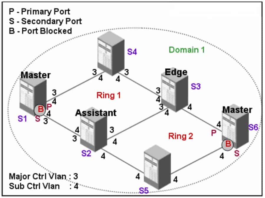
ERPS Control VLANs: Control VLANs are relative to data VLANs and are used only to pass ERPS protocol messages in an ERPS domain. Each ERPS domain is equipped with two control VLANs, the primary control VLAN and the sub-control VLAN. Direct ring protocol messages are propagated in the immediate control VLAN, and subring protocol messages are reproduced in the sub-control VLAN. The ports on each switch that accesses the Ethernet ring belong to the control VLAN, and only the ports that access the Ethernet ring can join the control VLAN. As the numbers 3 and 4 next to each port in the image above show, the ERPS port on the main Ring belongs to both the direct control VLAN and the child control VLAN; the ERPS port on the child ring belongs to the child control VLAN only. The primary Ring is considered a logical node of the subring. The messages of the subring are transmitted through the primary Ring; the news of the primary Ring is only propagated within the primary Ring and does not enter the subring. In contrast to the control VLAN, the data VLAN is used to transmit data messages. The data VLAN can contain either ERPS ports or non-ERPS ports.
Master Node: Each switch on an Ethernet ring is called a node. There must be a master node on each ERPS ring, and there can be only one, such as S1 in the figure above, which is the master node of the primary Ring, and S6, which is the master node of the subrings. The master node is the initiator of the Polling mechanism (ring state active detection mechanism) and the decision-maker to operate the network topology changes. The master node periodically sends HELLO (health detection message) messages from its master port, sequentially propagated through each transmission node on the Ring. If a HELLO message is received from the secondary port of the master node, the Ring’s link is complete; otherwise, if the HELLO message is not received within the specified time, the Ring is considered to have a link failure.
The master node has two states as follows:
Complete State: The master node is said to be in the Complete state when all links on the Ring are in the UP state, and the master node can receive its HELLO messages from the secondary ports. The state of the master node reflects the state of the ERPS ring, so the ERPS ring is also in the Complete state when the master node blocks the secondary port to prevent data messages from forming a broadcast loop on the ring topology.
Failed State: When all the links on the Ring are in Downstate, the master node is said to be in a Failed state when the master node releases the secondary ports to ensure that the communication of the nodes on the Ring is not interrupted.
Transmission nodes: All nodes on the ERPS ring except the master node are transmission nodes, e.g., S2, S3, and S4 in the above figure are transmission nodes of the master ring, and S5 is the transmission node of the sub-ring. The transport nodes are responsible for monitoring the status of their directly connected ERPS links and informing the master node of the link changes, and then the master node decides what to do.
The transport node has the following three states.
Link-Up State (UP state): a transport node is said to be in the Link-Up state when both its primary and secondary ports are in the UP state.
Link-Down State (Down State): a transmission node is said to be in the Link-Down state when its primary or secondary port is in the Downstate.
Preforwarding State (Temporary Blocking State): when the primary or secondary port of the transmission node is blocking, the transmission node is said to be Preforwarding.
A transport node in the Link-Up state migrates from the Link-Up to the Link-Down state when it detects a link down on the primary or secondary port and notifies the master node by sending a Link-Down message. The transport node does not migrate back to the Link-Up state directly from the Link-Down state. When a port of a transport node in the Link-Down state has a Link-Up, both the primary and secondary ports are restored to the Upstate, and the transport node migrates to the Preforwarding state and blocks the fixed port. When both the primary and secondary ports of the transmission node are restored, the primary node does not know this information immediately. Hence, its secondary port is still in the released state. Suppose the transmission node directly migrates back to the Link-Up state. In that case, it will inevitably cause data messages to form a broadcast loop on the ring network, so the transmission node migrates from the link down to the Forwarding state first. When the transmission mode in the Preforwarding state receives a COMPLETE-FLUSH-FDB message from the master node, it will relocate to the Link-Up state. Suppose the COMPLETE-FLUSH-FDB message is unfortunately lost during transmission. In that case, the ERPS protocol also provides a backup mechanism to restore the temporarily blocked port and trigger the state switch. If the transmission node does not receive the COMPLETE-FLUSH-FDB message within the specified time, it migrates to the Link-Up state and releases the temporarily blocking port.
Edge node and auxiliary edge node: When two rings intersect, there must be two intersection points; similarly, there will be two intersection points between the subring, and the main Ring, one of the switches at these two intersection points is called the edge node, and the other one is called auxiliary edge node. S3 is the edge node of the subring, and S2 is the extra edge node. There are no special requirements for which switch is configured as an edge node or secondary edge node, as long as it is configured to distinguish between the two nodes. The edge node or auxiliary edge node is the switch’s role on the subring, and its role on the primary Ring is that of a transport node. Both edge and auxiliary edge nodes are particular transmission nodes and have the same three states as transmission nodes. Still, with slightly different meanings, as follows: Link-Up State (UP state), an edge node (auxiliary edge node) is said to be in Link-Up state when the edge port is in UP state. link-Down State (Downstate), when the edge port is in Downstate, the edge node (auxiliary edge node) is in Link-Down state. The edge node (auxiliary edge node) state migration is the same as the transport node. The difference is that the edge node (auxiliary edge node) only cares about the edge port state when the port links state changes resulting in state migration (refer to the edge node state definition above). The edge node and the auxiliary edge node are the two subjects of the mechanism for detecting the channel state of subring protocol messages in the primary Ring. The edge node is the initiator of the agent, and the auxiliary edge node judges the channel state and reports it to the edge node. Finally, the edge node makes decisions and applies different operations according to the channel state, and this mechanism is described in detail later in the means for detecting the channel state of subring protocol messages.
Primary and secondary ports: The primary node and the transport node access one of the two ports of the Ethernet ring; one is the direct port, and the other is the secondary port. The user’s configuration determines the roles of the ports. The primary and secondary ports of the master node are functionally distinct. The master node sends a loop status probe message from its master port. If the message can be received from the secondary port, it means that the ERPS ring network in which this node is located is complete, so the secondary port needs to be blocked to prevent data loops; on the contrary. If the probe message is not received within the specified time, the ring network is faulty, so the secondary port needs to be released to ensure regular communication of all nodes on the Ring. There is no functional difference between the primary and secondary ports of the transport node. The user’s configuration also determines the role of the port. In particular, when the secondary port of the primary ring node is blocked, the data message and the protocol message of the sub-ring should be forbidden. In other words, the sub-ring protocol message is treated as a data message in the main Ring. As the secondary port of the primary node, the ERPS port (including the primary port and the secondary port) on the direct transport node will block both the data packets and the protocol packets.
Standard port and edge port: the edge node (the second edge node) is connected to the two ports of the child ring, one is the common, port, and the other is the edge port. The standard port is the port on the Main Ring and the sub-ring on the edge node (auxiliary edge node), and the edge port is the port only connected to the sub-ring. The concept does not regard the public port as the port on the sub-ring but believes it is a part of the main Ring, even if the public link is in the main ring link, not the link on the sub-ring. The state of the public association is reported only to the primary ring node; the child ringmaster node does not need to know. The user’s configuration determines the role of the standard port and the edge port.

Technology and Performance Comparison Demonstration (EAPS and ERPS)
Basic concepts.
EAPS (Ethernet Automatic Protection Switching) RFC-3619 and ERPS (Ethernet Ring Protection Switching). Fast Ethernet is used to ensure that data messages can be quickly sent when the topology changes by controlling MAC address aging to be sent to the correct link when the topology changes. In general, the MAC aging time is 300 seconds. The ring protocol can control the MAC address table aging rapidly, and the default is less than 50 milliseconds.
Principle comparison.
EAPS working mechanism: The master node periodically sends probe messages to the control VLAN and finally accepts them from the secondary port. The loop is standard and blocks the data VLAN of the secondary port by default. If the secondary port does not receive probe messages for some time, HEALTH means the loop is not working. The master node releases the blocking of the secondary port, ages the local MAC table, and sends the control message Ring -down-flush-FDB to notify other nodes. When the transmission node’s transmission port link fails, it sends the failure notification message Link-down through another port. When the primary node receives this message, it ages the local MAC table and sends the control message Ring-down-flush-FDB to notify other nodes.
ERPS working mechanism: The protection node blocks the RPL port and sends NR-NB protocol messages periodically in a stable state. All ordinary nodes that receive NR-NB messages set the local ring port to the forwarding state. When the protection node does not receive NR-NR telegrams for some time, it considers the link faulty and will immediately release the local RPL blocking state.
The faulty node then starts sending SF protocol messages for MAC aging. Other ordinary nodes that receive SF stop sending data and immediately unblock the local un-failed port for MAC aging. Only when the port of the failed node recovers and receives SF protocol packets again, the port return to the forwarding state.
Common Features of EAPS and ERPS
- Reversible protection reversal, that is, after the port link outage is eliminated, the protocol will return to the state before the reverse.
- EAPS and ERPS can be applied on the same switch, but they must operate on different rings and cannot operate simultaneously on the same Ring.
- Support SSTP, RSTP, EAPS, and ERPS coexistence, ring ports do not participate in STP calculation, and MSTP coexistence is not supported.
Different Features of EAPS and ERPS
ERPS industrial-grade ring switch networking advantages
The advantages of using ring networking for industrial-grade ring switches
- Ring switch networking is stable and has a short self-healing time.
- In the ring network construction, when one fiber is not available, you can automatically jump to another fiber optic cable to continue communication using the ring switch.
- The port resources and link bandwidth utilization of the ring switch network are higher.
- The network is more reliable after using a ring switch to build a ring solution.
Advantages of Ethernet switch tree networking with ring function
- Tree networking of Ethernet switches with ring function avoids communication protocols and is convenient for management.
- Tree networking of Ethernet switches with ring function can effectively avoid broadcast storms and ensure the regular operation of the switches.
- The Ethernet switch tree network with ring function has the advantages of high transmission bandwidth, flexible network structure, easy expansion, multi-service support capability, easy maintenance, and strong anti-interference.
- The tree network of Ethernet switches with ring function can realize redundancy protection.
The environment of the ring switch and Ethernet switch with ring function
Both ring switches and Ethernet switches with ring functions have their environment and advantages. Ring switches are mainly used in industrial sites and are suitable for harsh environments. In contrast, Ethernet switches with ring functions are more suitable for network construction in enterprise, data centers, metropolitan, and wide-area networks.
Conclusion.
HoweVision talks about communication; Mr. Hua analyzes the latest communication technology for you; Mr. Hua is willing to work with you to promote communication technology to a broader future! Today’s “Analysis of industrial ring network ERPS technology and value” is shared here; what kind of views do you have on the PoE switch heating problem? You are welcome to leave your message to Mr. Hua. Thank you for your review, more hot communication technology, and so on to read, next time again!


1 thought on “What is Industrial Ring ERPS Technology”
What i do not understood is actually how you are not really a lot more well-favored than you may be right now. You are so intelligent. You recognize therefore considerably on the subject of this matter, produced me in my opinion believe it from so many various angles. Its like men and women are not involved until it is one thing to do with Girl gaga! Your own stuffs excellent. At all times maintain it up! Darnell Andrepont
Comments are closed.